RFIDDiscover (formerly MifareDiscover) is a GUI software provided by NXP to help the developers explore the features of their contactless cards (Mifare, Desfire, NTAG and ICode) and learn how-to use them from a real application.
This software is available to customers under NDA with NXP, through the DocStore document delivery platform (ref. SW1866).
This article shows how-to get started with this RFIDDiscover, in the aim of using it together with SpringCard devices. This is the preferred method to learn how those cards work, before starting the development of any software that would use them for data storage and/or secure transactions.
Remark
A Lite version of RFIDDiscover is available to anybody who is registered on MIFARE.NET, a web site provided by NXP to structure a community of implementers and developers, but, unfortunately, RFIDDiscover Lite lacks supports for PC/SC couplers (it works only with the low-level evaluation boards of a few NXP RF/NFC chipsets). Please contact your NXP sales representative to get access to the full version of RFIDDiscover.
Disclaimers
SpringCard is not affiliated, endorsed by, or sponsored by NXP. This article points to services and information that are covered by a license agreement and/or a non-disclosure agreement to be signed between you and NXP. SpringCard provides this article “as is” at the date of writing in the hope that it will be useful – no updates nor support will be provided.
Obtaining and installing RFIDDiscover
Once approved by NXP, download the software from DocStore and install it on a Windows computer.
Running RFIDDiscover for the first time and enabling SpringCard readers
Upon start-up, RFIDDiscover prompts to select a reader:
Unfortunately, at this step, the software will not show the SpringCard PC/SC readers in the Contactless Reader Selection list. Click Cancel to access the main form.
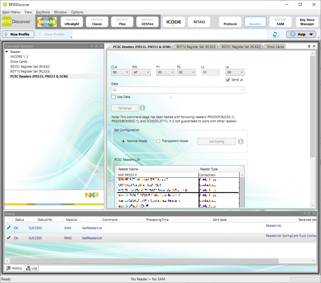
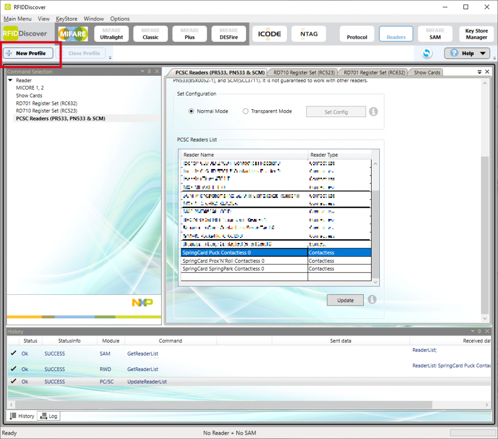
Locate the PCSC Readers List block un the PCSC Readers tab, and a line for every SpringCard PC/SC reader you want to use.
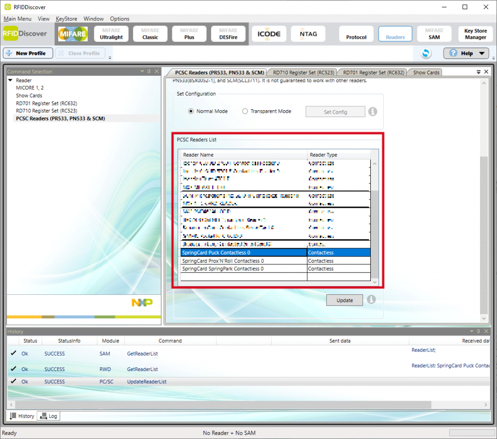
In the above example, we’ve introduced 3 readers to the software:
- SpringCard Puck Contactless 0
- SpringCard Prox’N’Roll Contactless 0
- SpringCard SpringPark Contactless 0
Note that the 0 at the end of the reader’s name is its index in the PC/SC system. If you have more than one SpringCard device connected to the computer, the second will show 1 in its name, the third 2, etc. Use PCSCDiag2 from the PC/SC SDK and Quickstart to know the actual names taken by the devices that are currently connected.
Click the Update button when finished.
Now click New profile to open the select reader form again.
The Contactless Reader Selection list now shows the SpringCard readers (in the following snapshots, we’ll use a Puck).
Select the SpringCard Contactless reader.
Before clicking OK, place the contactless card you want to use on the reader’s antenna. Since RFIDDiscover uses SCardTransmit function calls only, it is not able to use a PC/SC reader that has no card in it (in the following snapshots, we’ll use a Mifare Plus EV1).
Normal mode or Transparent Mode?
Once connected to the reader (with a card in it), you must choose (and therefore understand) whether you want to operated in Normal Mode or in Transparent Mode. Let’s use an example to explain the meaning of this parameter, and the differences between the two modes.
Normal Mode
In this mode, all the commands are transmitted ‘as is’ directly to the card, through the reader. The software assumes that the complete PC/SC stack (WinsCard library, middleware service, driver and coupler) are able to convey any command without any constraint over its format, and that the coupler is able to handle the card’s protocol on its own.
This is perfectly true when the card is compliant with ISO/IEC 14443 layer 4 “T=CL”, as we can see in the example below with our Mifare Plus EV1 card that is still in Security Level 0 (supporting layer 4 only).
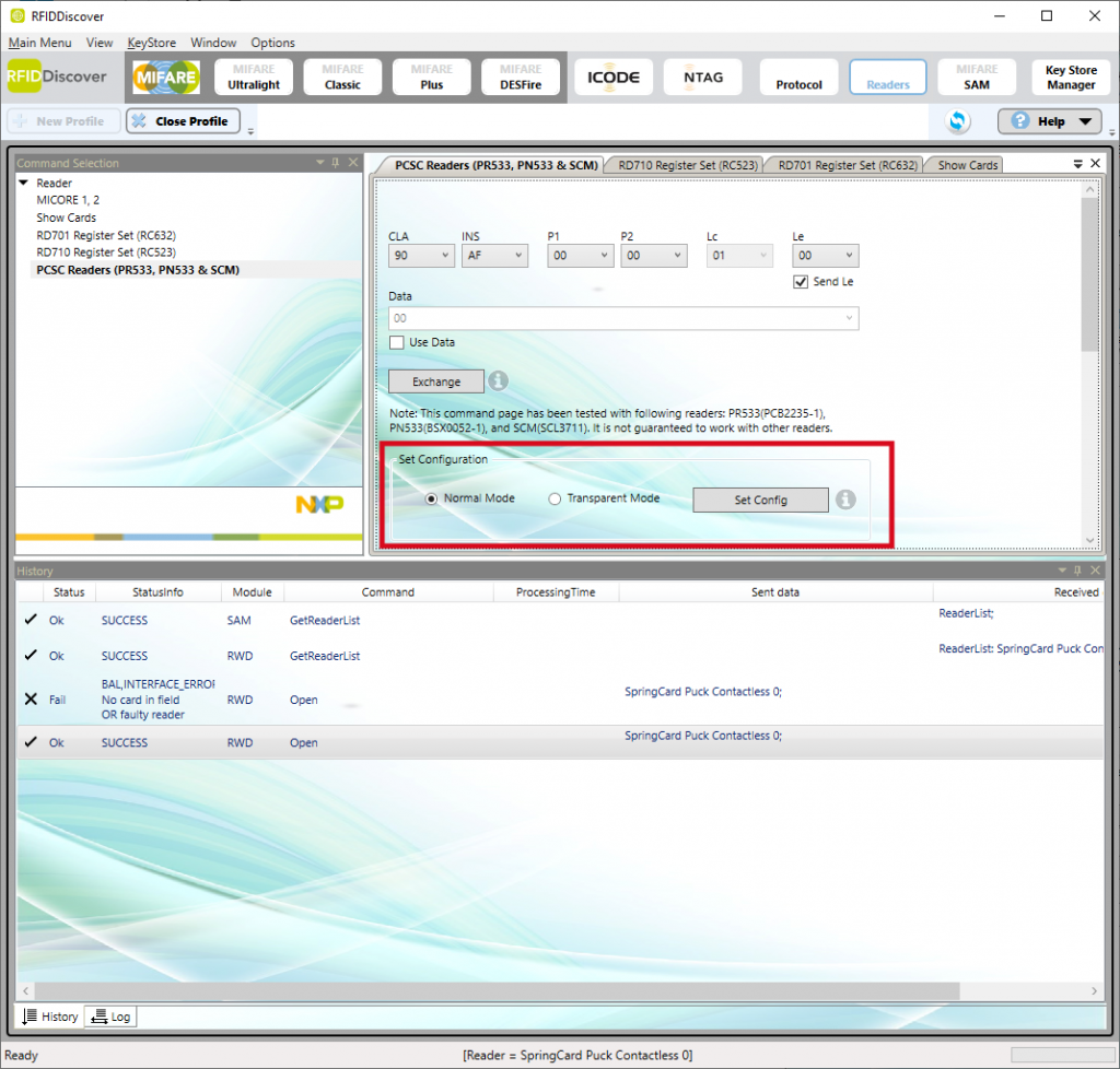
1. Choose Normal Mode and click Set Config
2. Click MIFARE Plus button in the upper band to open the Mifare Plus panel
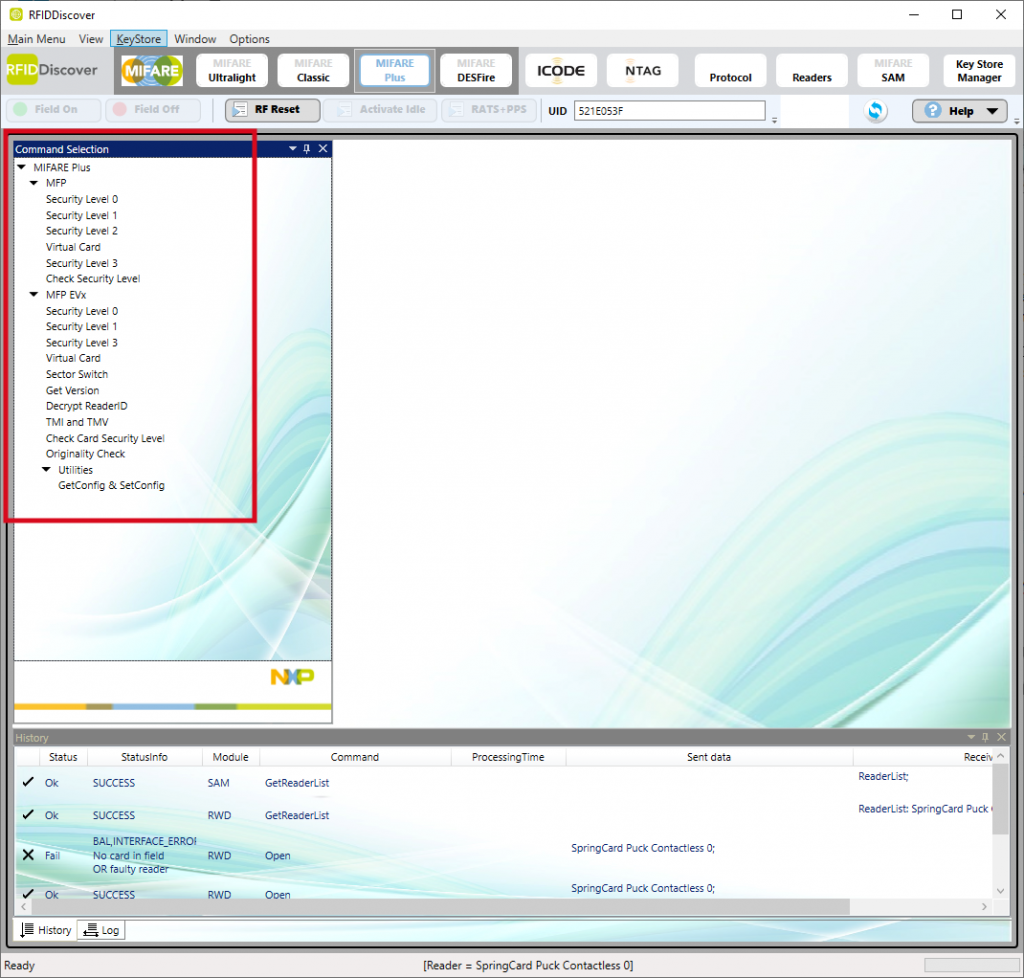
3. Expand the tree in the Command Selection panel,
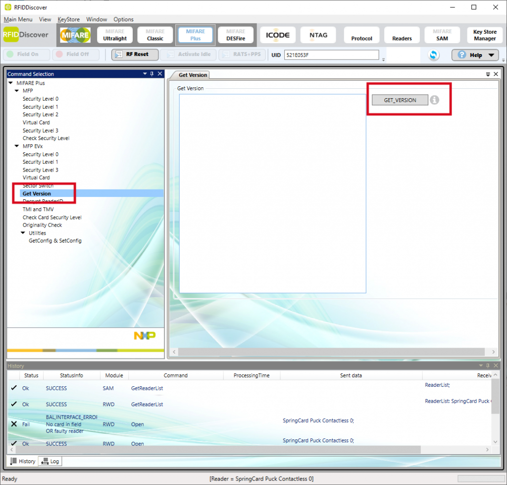
4. In the tree, choose MIFARE Plus / MFP EVx / Get Version
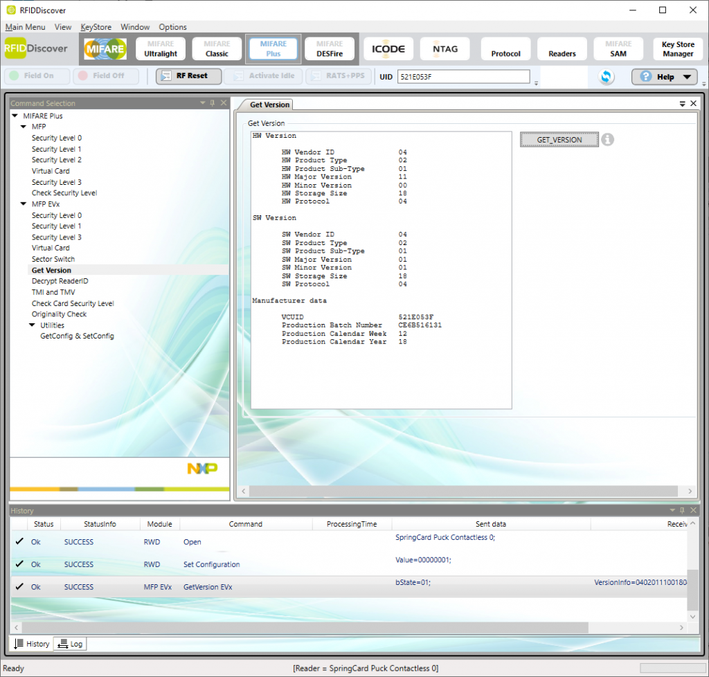
5. The GET_VERSION button, the software reads the version information from the card and displays the result:
To understand the actual difference with the Transparent Mode that will be detailed below, we must have an access to the APDU sent by the application to the card (through the coupler) within SCardTransmit calls. Unfortunately, RFIDDiscover does not reveal its APDUs, so we had to use another method to spy them. We also used a RF Spy tool to record the RF communication between the coupler and the card.
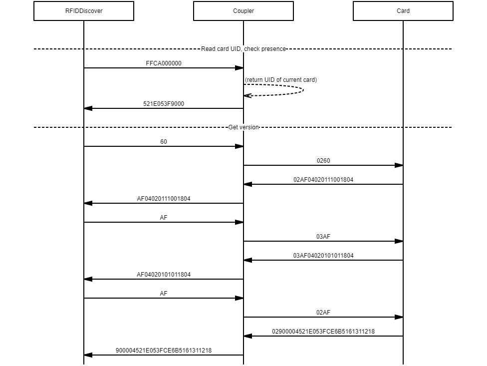
Here’s the detail of the exchanges:
At first, the software sends FFCA000000 which is the PC/SC-defined APDU to get the card’s UID (for reference, see GET DATA instruction in the documentation of the SpringCore devices).
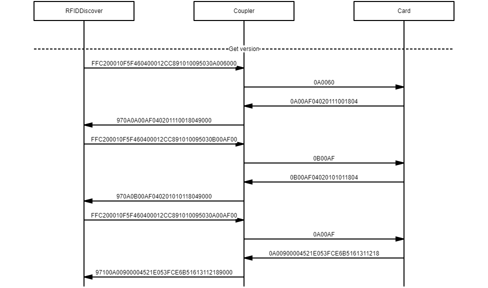
Then, the software sends single byte 60 that is the opcode to the GET VERSION command of the Mifare Plus card. The coupler maps with very short APDU into a TPDU by adding a header (PCB=02 / PCB=03). The card’s response is split into 3 parts; the AF opcode is the chaining indicator.
This sequence works because the SpringCard driver and coupler are able to take the 60 or AF single-byte application-level datagram units (literally, APDUs) and transmit them to the card in ISO/IEC 14443-4 blocks or transport-level datagram units (TPDUs). This work with SpringCard devices, but this is not the case of all couplers on the market because the PC/SC standard assumes that all the APDUs follow the ISO/IEC 7816-4 format (CLA, INS, P1, P2 …) which is obviously not the case for Mifare Plus cards.
Before leaving the Normal Mode for the Transparent Mode, just note that the Field On and Field Off buttons are disabled, as well as the Activate Idle and RATS+PPS buttons.
The RF Reset button is the only-one that is enabled, but it does not exactly perform what the name says: actually, it closes the connection channel with the current/previous card (SCardDisconnect) and opens a new channel, either to the same card or to another card if it has been changed in the meantime (SCardConnect). Then, it reads the UID of the new card (SCardTransmit FFCA000000).
For instance, here we have replaced the Mifare Plus by a Desfire:
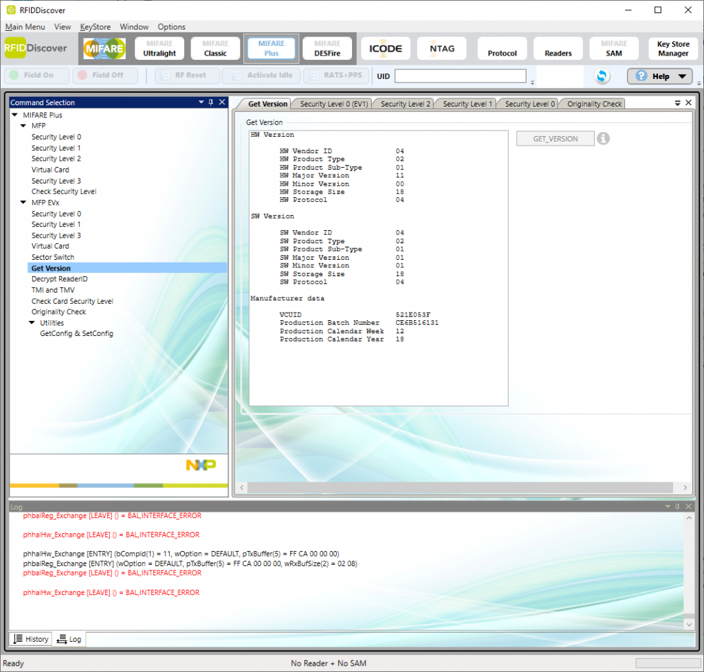
And here we have removed all the cards:
We must then go back to the Readers panel to re-select the reader because RFIDDiscover is unable to operate without a valid card channel. Note the BAL,INTERFACE_ERROR message in the Log panel.
Transparent Mode
To activate the Transparent Mode, go back to the Readers panel:
1. Choose Transparent Mode and click Set Config:
2. Go back to the MIFARE Plus panel:
3. Note that all the low-level control buttons are now active:
4. Click RF Reset, Activate Idle and then RATS+PPS
5. Click GET_VERSION; the software retrieves the card’s version info again.
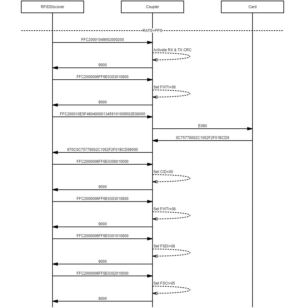
The detail of the exchanges recorded by our two spies are depicted below, and they are totally different from the ones in Normal Mode.
Part 1: RF Reset
In Transparent Mode, RFIDDiscover directly instructs the coupler to perform a RF field reset. This is done using PC/SC-defined ENVELOPE instruction (CLA=FF, INS=C2). The embedded APDU interpreter running inside the SpringCard device decodes the instruction’s data and execute the required action.
This is different from Normal Mode where only the SCardConnect / SCardDisconnect where called instead.
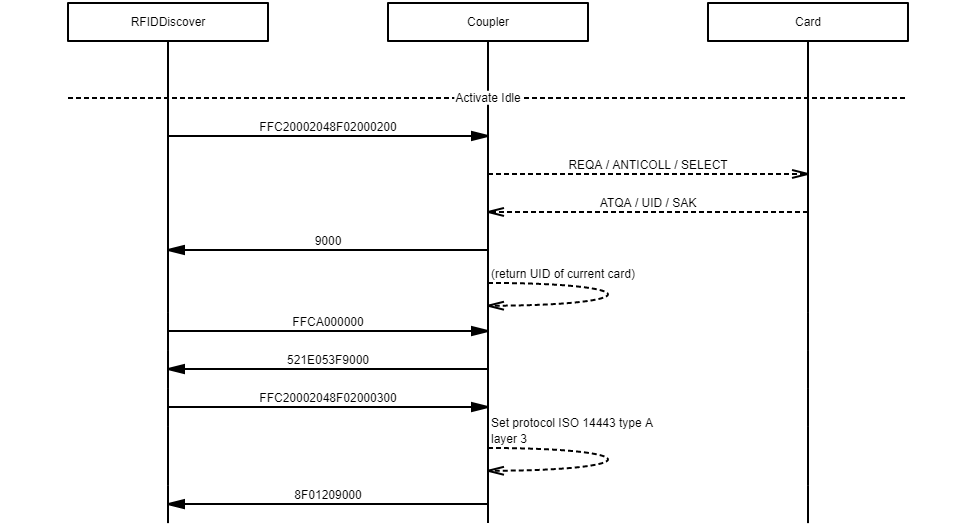
Part 2: Activate Idle
In Transparent Mode, RFIDDiscover instructs the coupler to run an ISO/IEC 14443-A activation sequence (REQA / ANTICOLL / SELECT). The card returns all its protocol data (ATQA / UID / SAK). Again, this is done using PC/SC-defined ENVELOPE instruction (CLA=FF, INS=C2). Afterwards, RFIDDiscover confirms that the coupler should stay at layer 3 (no T=CL activation).
This is different from Normal Mode where the card is activated at layer 4 (T=CL) to be operated directly at APDU level.
Part 3: RATS+PPS
In Transparent Mode, RFIDDiscover feeds the coupler with all the low-level transmission parameters, and uses a transparent exchange (ENVELOPE instruction, CLA=FF, INS=C2, with P1,P2=00,01) to send the command E080 (RATS) to the card. The card then provides its ATS (0C7577…D6) and enters layer 4 (T=CL), but from the coupler’s point of view, the card is still a layer 3. The T=CL transport (TPDUs) has to be completely implemented in the software.
This is different from Normal Mode where the coupler is responsible for mapping APDUs into TPDUs.
Part 4: GET_VERSION
In Transparent Mode, RFIDDiscover uses transparent exchanges to send the TPDUs to the card.
Again, this is different from Normal Mode where the coupler is responsible for mapping APDUs into TPDUs.
NB: the difference in TPDU format is due to RFIDDiscover using CID=00 (card identifier) where the coupler’s “normal” T=CL implementation works without CID by default. The header assembled by RFIDDiscover are therefore PCB=0A,CID=00 / PCB=0B,CID=00 instead of PCB=02 / PCB=03 when assembled by the coupler.
Conclusion
The RFIDDiscover application by NXP is an interesting tool to get familiar with the low-level implementation of their cards and tags (not only Mifare Plus EV0 and EV1, but also Desfire EV1, EV2, EV3 and Light, Mifare UltraLight EV0, EV1 and C, and of course the still popular Mifare Classic, as well as NTAG and ICODE).
Thanks to the transparent mode, RFIDDiscover allows to go deeper inside the implementation details of the tags and RFID labels than Card Test Framework.
Since the software works well with SprinCard PC/SC couplers, such as Prox’N’Roll, Puck, and more, there’s no need to buy a dedicated test reader to explorer those cards.


