This document explains how to upgrade E663′s and the Funkygate-IP firmwares, using the Renesas Flash Development Toolkit (FDT).
Please read the datasheet of every product for specifications and the detailed list of features.
Important disclaimer:
Please note that SpringCard is not responsible for any procedure that end user performs. Please note that not products can be recovered from improper firmware upgrade or mis-configuration !! YOU’RE FOLLOWING THIS PROCEDURE AT YOUR OWN RISK.
Getting started
Requirements
To be able to upload your firmware properly on the E663/Funkygate-IP modules, you need a computer running on Windows Xp/Vista/7. You will also need at least one working USB port and, of course, a Springcard product featuring a E663/S663 module in flash mode.
Except if the reference of your reader ends with something greater or equal to XXXX-AE, be sure to remove all power supply sources (external DC or POE) when connecting the reader to the computer through USB.
Register on Renesas Website
This registration will be necessary to download Flash Development Toolkit. Please browse to : http://www.renesas.eu/
Download and install Flash Development Toolkit
Download and installation
Once the registration is complete, you can download the last Flash Development Toolkit “Release” (and not “update”) Version (currently v4.09) on the FDT download page:
You will then have to run the downloaded launcher and install FDT with all the default options.
Download latest firmware’s version
For E663/RDR (Smart Reader version, i.e. FunkyGate-IP NFC) : E663/RDR.
For E663 PC/SC (FunkyGate-IP PC/SC, TwistyWriter-IP PC/SC) : E663.
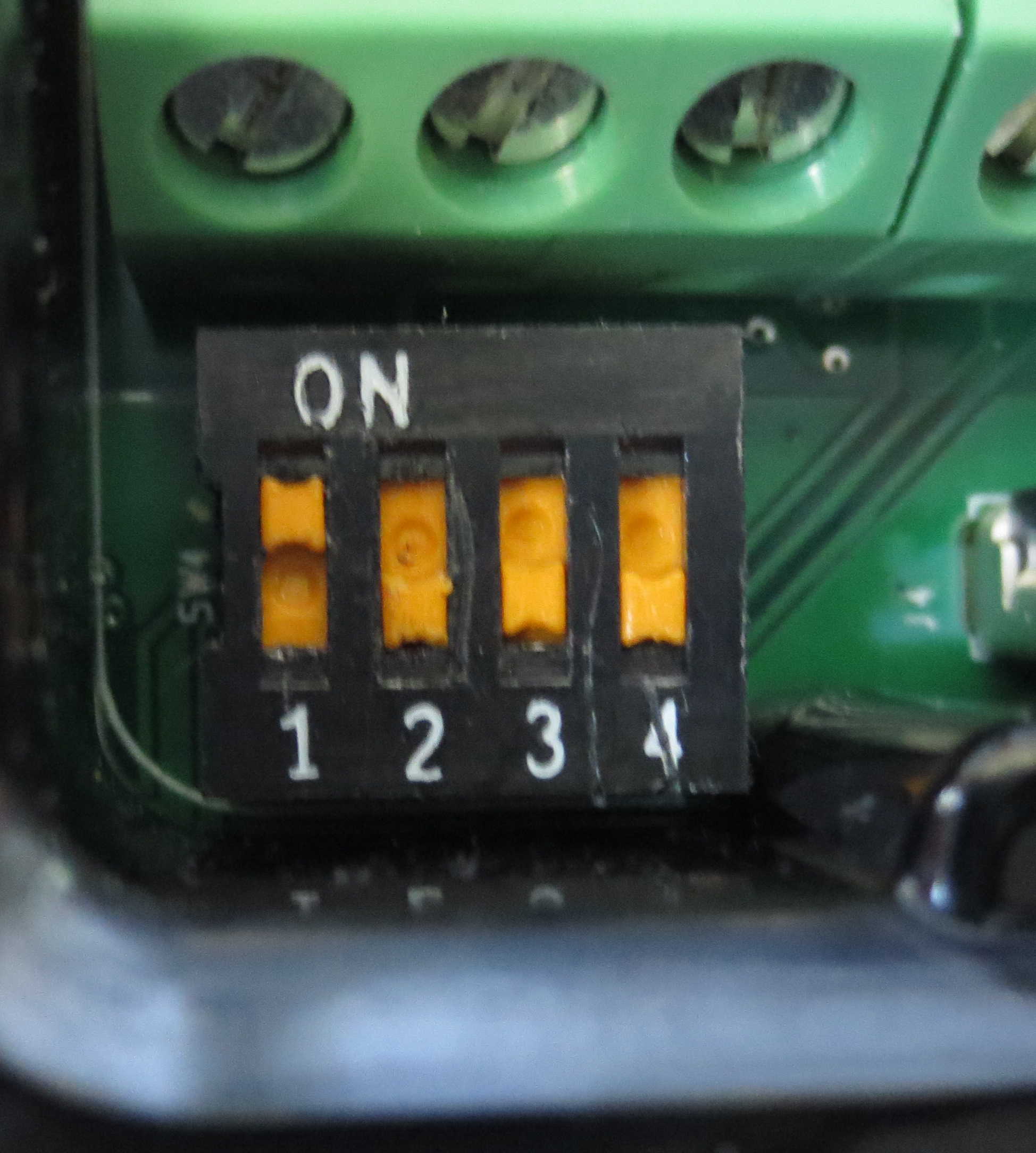
Ensure your device is ON and in Flash Mode
Make sure your device is not powered – remove Ethernet cable and shutdown DC power supply.
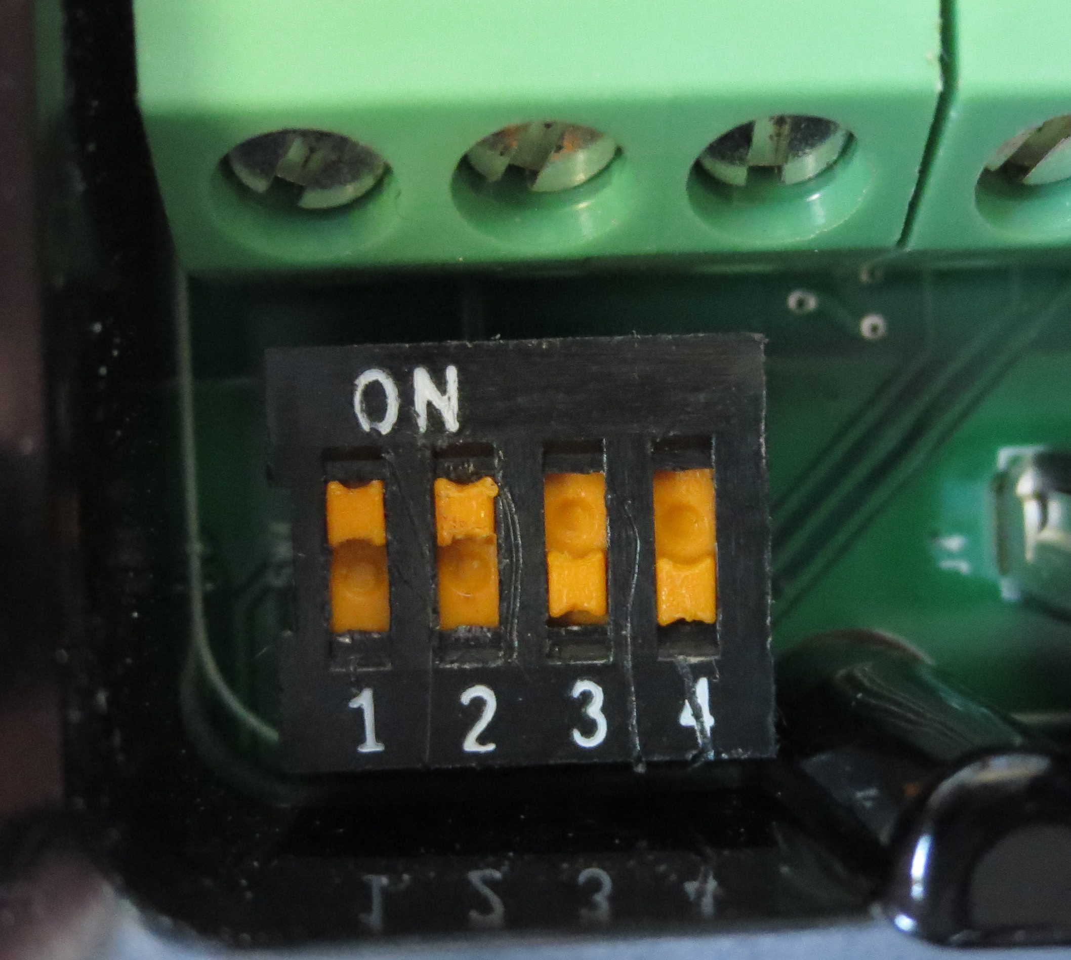
To enable flash mode, the switches must respect the following pattern :
- 1 – ON
- 2 – ON
- 3 – OFF
- 4 – OFF
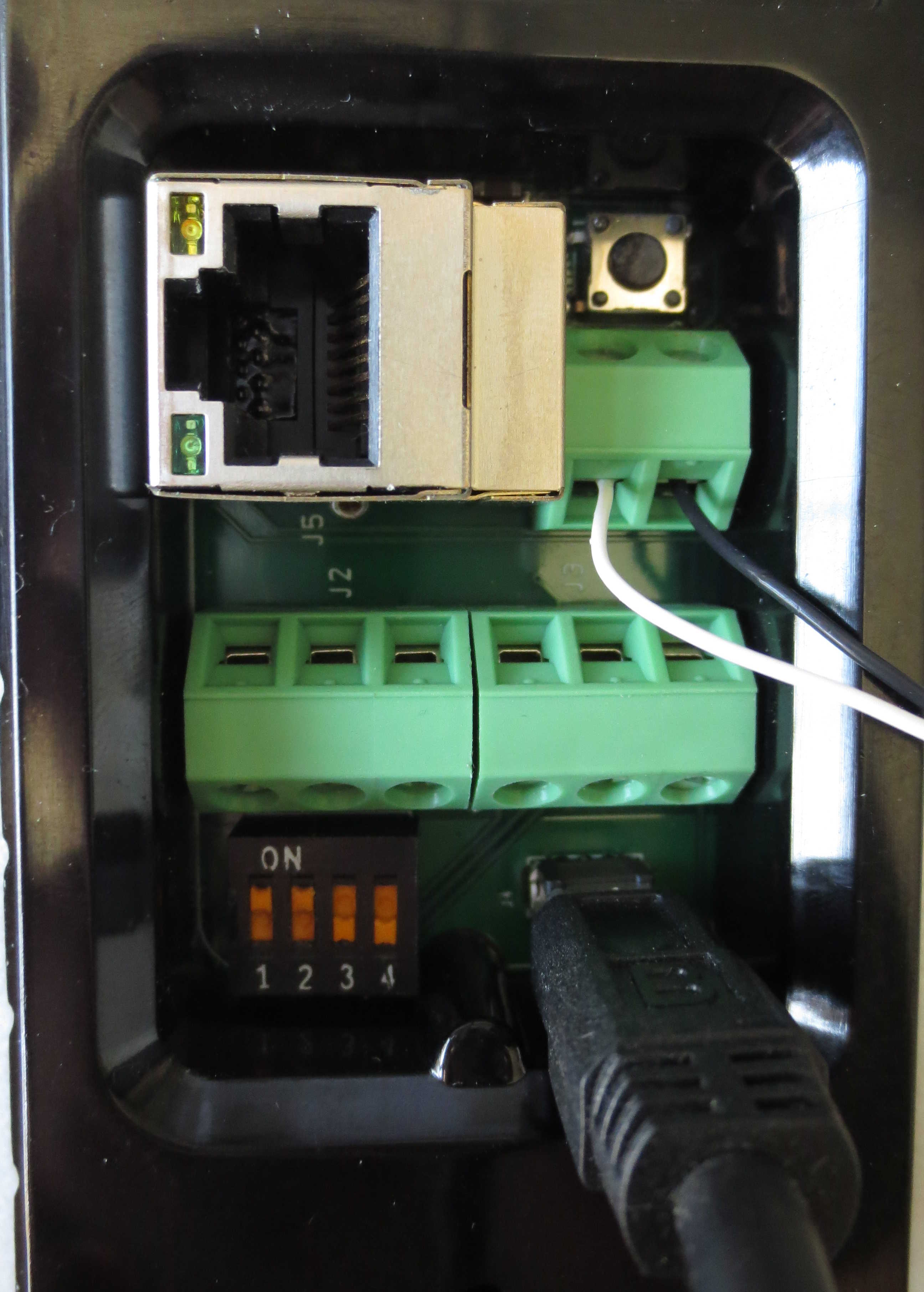
When the switches are in correct position, connect the device to a computer’s USB port using a standard cable (mini-type B on reader side).
Wait until the USB Direct driver installs automatically.
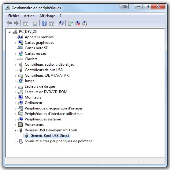
Your reader must appear as Generic boot device in the Windows’ peripheral management.
If your reader does not appear in the list and if its reference ends with something greater or equal to XXXX-AE, then you have to connect it to a power supply source (external DC or POE).
Recent versions of the Funkygate do require a power supply to be flashed.
Create a new FDT firmware upgrade project
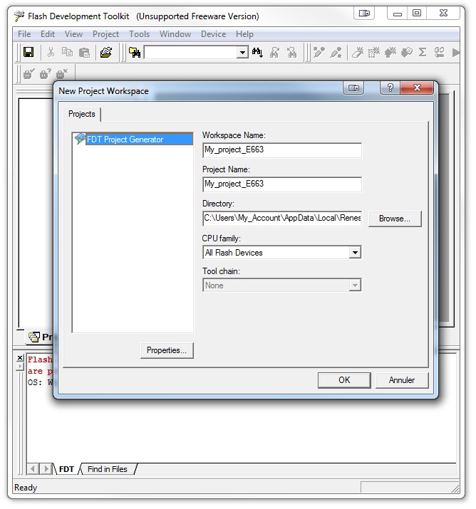
- Launch the FDT application. A Welcome window will allow you to “Create a new project workspace“. Click “OK” to continue.
- New Project Workspace.
You will have to input the “Workspace name“ and “Project Name” of your choice and specify a valid project directory path. Ignore “CPU familly” and click “OK” to continue.
- Choose Device And Kernel.
Select “Generic BOOT Device” at the bottom of the scroll down control and click “Next” to continue.

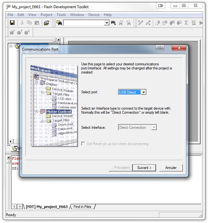
- Communication Port.
On the “Select port” control, please select “USB Direct“ and click “Next” to continue.
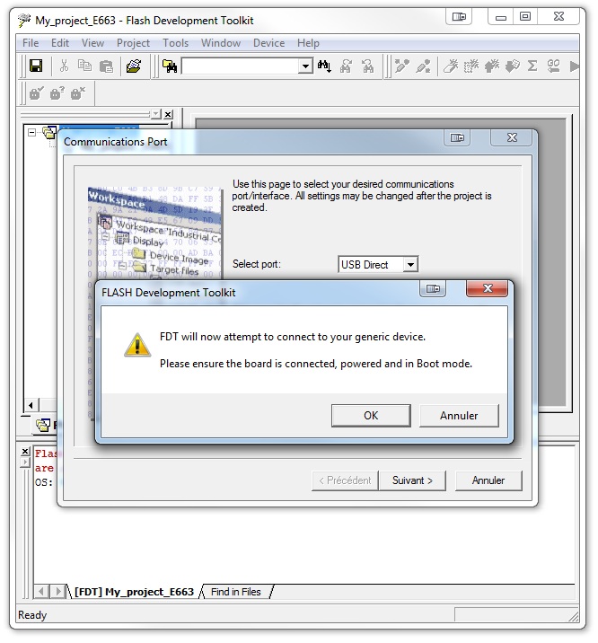
After this step a “Flash Development Toolkit” popup will appear. Click “OK” to continue. If at this step your device does not appear in the pop-up windows, you should check if the proper driver has been installed. FDT should have already enabled a “Generic Boot USB Direct” driver. If it is not the case, look for it when the Windows Driver installation popup appears when you connect your module in flash mode.
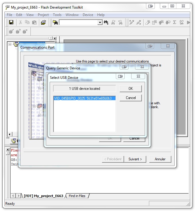
- Select USB Device. (1 USB device located). The reader must be already selected. Click “OK” to continue.
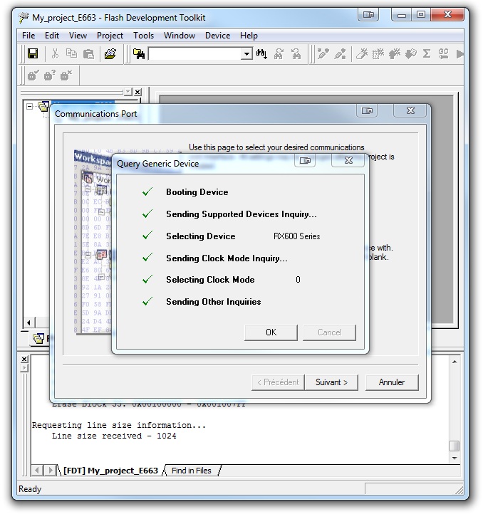
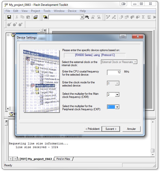
- After some automatic configurations, you will enter the Device Setting step. Enter “12.00MHz” for the CPU frequency, “2” for the Main Clock Frequency multiplier and “1” for the Peripheral Clock Frequency multiplier. Then click “Next” to continue.
- Programming Options. Keep default settings then click on “Finish”.

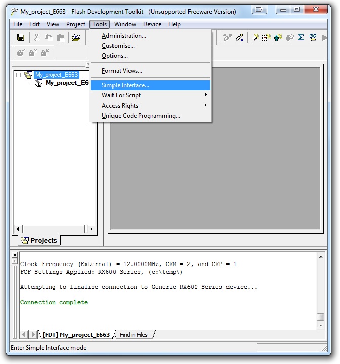
The firmware upgrade tool configuration is now over. Select Tools >> Simple Interface to simplify the project view.
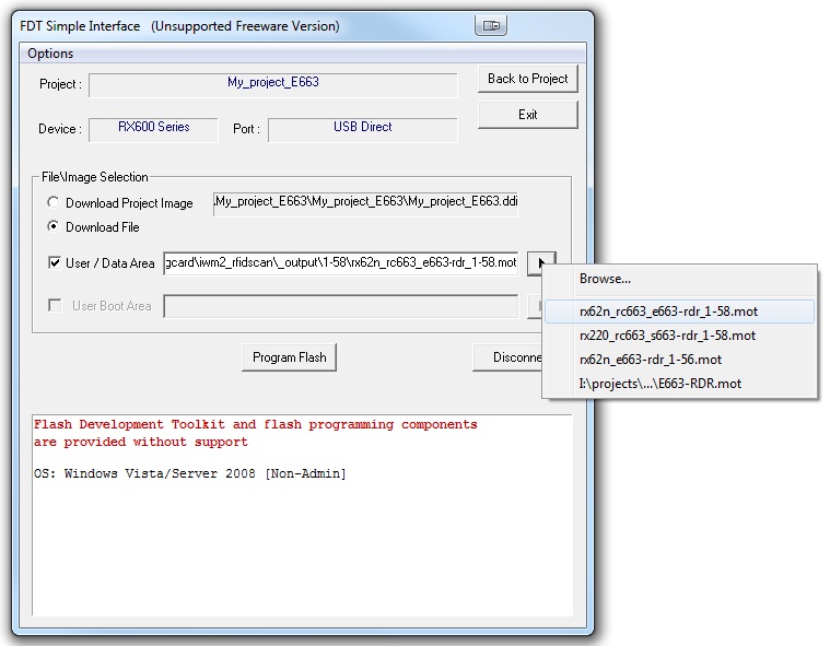
 You can now specify the firmware binary in the “File/Image Selection” by selecting the “Download File” radio button then the “User/Data Area” checkbox and endly by clicking on the play button to browse the firmware file.
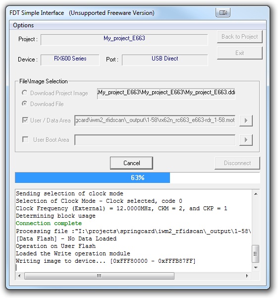
You can now click on “Program Flash” to load the new firmware in the reader’s flash memory and then on “Disconnect” to end the procedure.
Once the flash step is over, you can put your reader in play mode by setting the switches in the folowing configuration :
- 1 – ON
- 2 – OFF
- 3 – OFF
- 4 – OFF
Just press the RESET button and your reader is ready to be used!