An HF NFC/RFID reader or coupler usually spends most of its operating time waiting for a contactless card to arrive.
To detect this arrival, the reader or coupler must
- ensure continuous or quasi-continuous transmission of its carrier, since it is its own RF field (magnetic waves) that remotely powers the card,
- send search frames in an un-interrupted loop, using all the protocols it supports (REQA/WUPA, REQB/WUPB, Anticall, SENS_REQ, etc), to give the card the opportunity to respond as soon as it has been powered-up.
Obviously, this means that most of the operating time consists of… wasting a lot of energy, just to wait.

The Tartar Steppe (Il deserto dei Tartari) is a novel by Dino Buzzati, that tells the story of an officer, who spends all his energy waiting for the arrival of a contactless card. Well, not exactly, but, you’ve got the idea.
In the SpringSeed M519 module, and also in most other SpringCore products, the card waiting policy (polling policy) can be optimised to reduce the average power consumption of the product.
In highly demanding use cases, the LPCD (low-power card detection) feature can even dramatically reduce standby power requirement, to less than 10mA (however, this comes at the price of some implementation constraints, which you must be aware of before using this mode).
In this article, we will detail the different power-saving modes supported by the M519, and how to implement them on a M519-SUV. Obviously, the article also directly covers all the other products based on the M519, such as the M519-USS, M519-USA, etc. Regarding the other SpringCore products, there may some differences in the specifications of the products (absence of LPCD in particular), but most of the information may also apply to them.
Enabling low-power modes
The polling strategy is configured via bits 2 and 3 (mask 0x0C) of register 0x0230. This register also controls the tracking strategy, which we will explain in another article.
Detailed documentation on this register is available at
https://docs.springcard.com/books/SpringCore/Non_volatile_memory/Configuration/Contactless/General
The recommended way of editing the configuration is to use the SpringCard Companion software. SpringCard Companion provides a complete, simple and reliable GUI (reliable in the sense that it prevents you from creating inconsistent configurations).
The parameter we’re interested in is located under the General configuration of the Contactless (NFC) interface in poller (reader) mode group, and is called Polling policy.
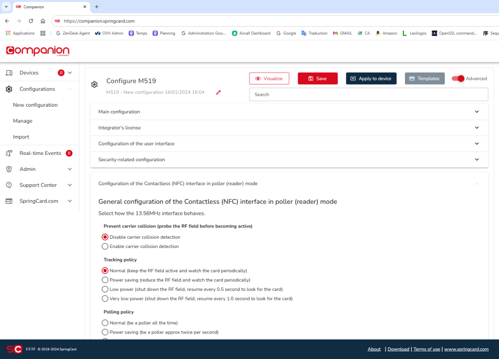
Of course, it is also possible to manipulate this register directly using the SpringCore Tools utilities, or by invoking the WRITE CONFIGURATION instruction directly from your own application, but this requires greater care to avoid pushing an inconsistent configuration into the product.
NB: in the rest of this article, we will use the M519 in PC/SC mode (register 0x02C0=0x02), but all the settings concerning the polling strategy would produce the same effects in Smart Reader and RFID Scanner mode.
Observation of average power consumption with default settings
Before looking at the effects of choosing a ‘low power’ mode, we’ll start by looking at the default operation of the product, which is delivered with register 0x0230 set to 0x01, i.e. the ‘normal’ setting.
We’ll use a small tool to measure the voltage and current drawn on the USB (it’s easier than cutting the VBUS line to insert an ammeter). The limitation of this tool is that it cannot give an average, even a sliding average. It simply takes one measurement per second. More advanced tools are therefore needed to measure the typical, averaged consumption. But for the moment, let’s work with orders of magnitude; this is already enough to get an idea of how to optimise the product.
We can see that the M519-SUV is powered at around 4.9V. In polling mode, without a card, the measure is sometimes 7mA, sometimes 230mA or 240mA, depending when the measure is taken, for the coupler is continuously looping between different internal states. You need to use the accumulator, which totals the number of mAh, and divide by the time spent to get a relevant value (it’s namely 140mA according to the datasheet).
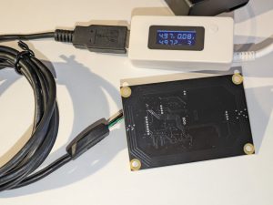
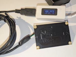
By placing a contactless card in the field, we can already see that the power consumption is stabilizing to 240mA or 250mA, because the internal state is now stabilized on the ‘card present’ state.
It’s easy to see that the contactless card (here a Desfire) consumes very little power, since the value shown with the card is not different from the value shown previously without a card. The coupler plus the card, together, consumes not more than the coupler alone. Magic!
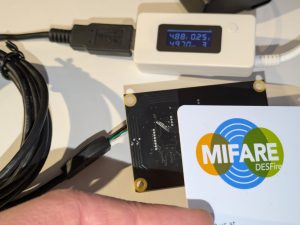
Actually, there’s no magic: the extra power drained by the card remains below the sensitivity of the tool, that’s all.
Another interesting observation: the position of the card affects the power consumption of the device: the closer the card, the higher the current.
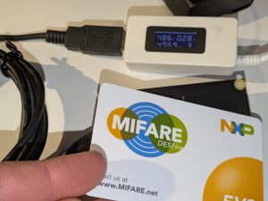
If you bring the card as close as possible to the antenna of the M519-SUV (really 0cm), consumption rises up to 280mA or 290mA. However, technically, we can assume that the chip of the card hasn’t decided to consume more power only because it has been moved closer!
This is known as the loading effect. The coupler antenna no longer resonates at the right frequency because of the effects of the card antenna (mutual inductance). The antenna is out of tune, which lowers the impedance seen by the generator, hence the increase in power consumption.
Remark
Let’s take this opportunity to make a brief aside.
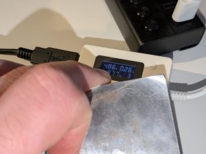
If you put a dumb iron block in front of the antenna, into which the RF field can dissipate as eddy currents, you’ll see that the consumption rise to 320mA, before decreasing and stabilizing to 260mA. In fact, the impedance drop is so strong that if there weren’t any protection circuits in the coupler, the consummation would rise even more (320mA triggers the limitation, 260mA is the current with limitation active). We’d call that an induction cooking hob.
But let’s stay on our topic. Next question is: what will happen if we configure the polling differently?
First thing to do to reduce power consumption: shorten the polling sequence
When we look at what can be configured in register 0x0230, we can already guess that the strategy for optimizing consumption will involve reducing the time spent in the polling loop, i.e. changing the cyclic ratio between the active RF field + polling state and the pause time, inactive RF field state.
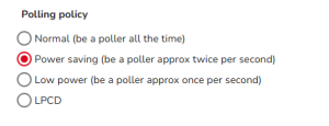
In practical terms, in the first power saving mode, the polling loop will only be executed every 500ms, and in the second mode, every second. The compromise is as follows: you have to accept a loss of responsiveness in order to save energy. We’ll come back to this in the next section.
But the very first saving to consider is to reduce the length of time the RF field is active, i.e. to reduce the length of the polling sequence. To do this, you need to start by disabling all the protocols you are not using. This is done using register 0x0231, or the NFC / RFID HF protocols enabled in PC/SC mode section in SpringCard Companion.

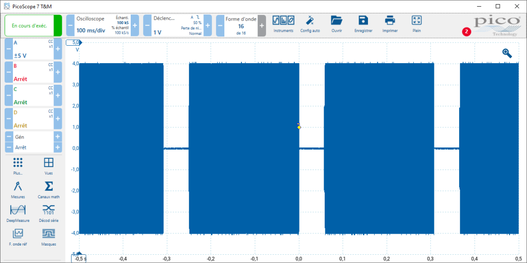
The oscilloscope observation above shows that the complete polling sequence lasts 250ms. The M519 then pauses for 55ms, field off, before looping. But if we know that we are only going to work with Desfire cards, we will only keep the ISO/IEC 14443-A protocol enabled.

This gives a totally different picture!
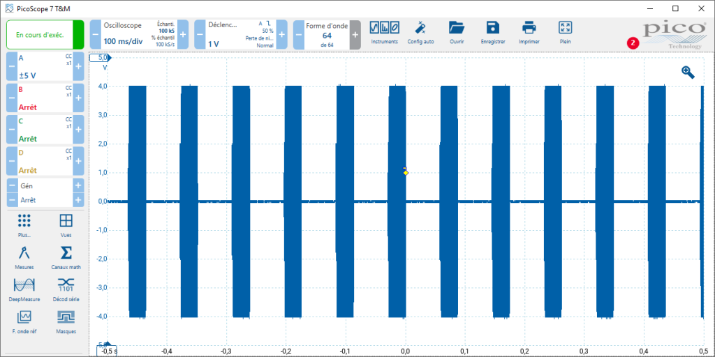
The oscilloscope observation above shows that the polling sequence now lasts 30ms only. The M519 still pauses for 55ms, field off, before looping.
Remark
To really go into all the sordid details, we can argue here that, with only the ISO/IEC 14443-A protocol enabled, the polling sequence could be shorten to as little as 10ms, while remaining absolutely compliant with the standard.
However, some cards that are in circulation in the field (especially the ones which have been designed 2 to 3 decades ago) generally need a reader that is ‘a little’ more accommodating than the standard. There is also the case of NFC smartphones: although they can perfectly emulate the upper layers of a contactless card, most of them still behave a little differently in the lower layers: some take longer to get activated, and some expect to be activated during a “long” period before activating high-level NFC applications.
Therefore, a conservative analysis of our feedback from products deployed in the field suggests that we should not over-optimise polling (which is obviously an essential function), hence the 30ms duration for a burst with only ISO/IEC 14443-A enabled. However, customers who want to go further should be aware that fine-tuning the firmware to the limits of the standard is actually possible, if they’re really convinced that it’s a good idea for their use-case.
The important thing to note is that the duration of the polling burst is divided by more than 8! Yet it continues to run at 55ms intervals, which also improves the product’s responsiveness, for an iteration of the loop is now completed in 85ms instead of 305ms.
But since the active/inactive duty cycle has been reduced from 82% (250/305) to just 35% (30/85), this already represents more than a 50% reduction in the energy consumed by the NFC / RFID HF interface during its card waiting periods. We can easily deduce from this that the average consumption has fallen below 70mA (even with the “normal” polling policy).
This is also visible on our little measurement tool, which now spends more time at 7mA or 10mA than 230mA or 240mA.
Operating in ‘power saving’ and ‘low power’ mode
Now that we have ensured that our polling loop is no longer than necessary, we can consider running it less frequently.

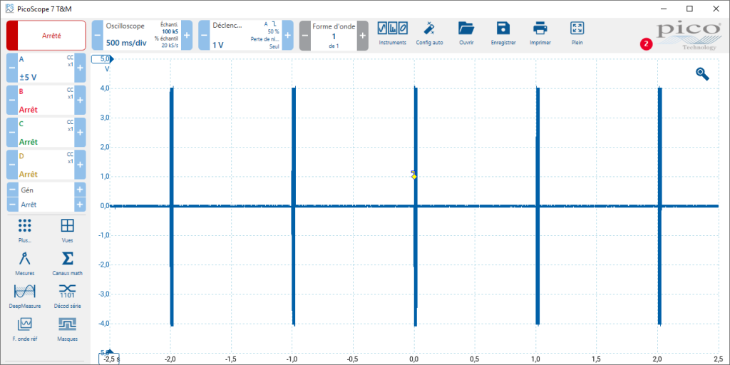
The ‘power saving’ setting consists of timing the operation of the coupler so that it makes at most two loop turns per second, i.e. a period of 500ms. The duty cycle is then reduced to 6% (30/500). The averaged consumption is now under 15mA.


The ‘low power’ setting consists of timing the coupler so that it makes no more than one loop revolution per second, i.e. a period of 1000ms. The duty cycle then falls to 3% (30/1000). The averaged consumption is now under 10mA.
LPCD mode
The NFC/RFID HF frontend of the M519 module is capable of performing low-power card detection. This deserves some technical explanations.
The core idea behind Low Power Card Detection (LPCD) is to completely deactivate the RF field when no card is present, in order to save as much energy as possible so that battery-powered HF NFC/RFID products can be designed. This requires a mechanism to detect the presence of a card without the need to provide remote power or to send polling requests. This can be done using an external sensor: an infrared or capacitive approach detector, a laser sensor with time-of-flight detection, or simply a trigger button or switch that activates when the card is in position.
But it’s also possible to exploit a phenomenon we mentioned earlier, linking it to induction hobs: the approach of a card causes a change of the impedance seen from the antenna driver of the coupler. This change in impedance is the result of antenna detuning (mutual inductance with the card’s antenna) and what comes under the heading of static consumption (loading effect) of the chip, even before it has started booting.
Here’s how it’s implemented in the M519: the NFC/RFID HF frontend activate its carrier very briefly and at a low level periodically (4 times per second in the case of M519).
This carrier burst is generally too weak to make the chip boot, and in any case it probably doesn’t even last long enough for its power supply circuit to stabilise.
But all that matters for the coupler is being able to assess the amplitude of the field, to determine whether it has changed since an earlier calibration burst.
If the amplitude has varied since calibration, all other things being equal, we can conclude that the electromagnetic environment is no longer the same. The field is then activated at full power and the polling sequence is executed, so we can see whether it is indeed the arrival of a card that has caused this change in the environment. If this is not the case, the module re-enters the LPCD mode immediatly.
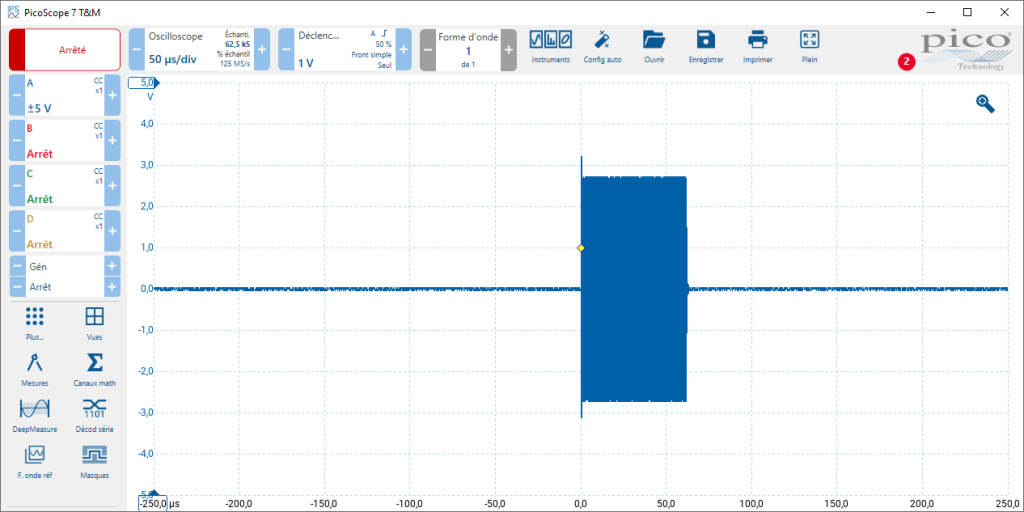
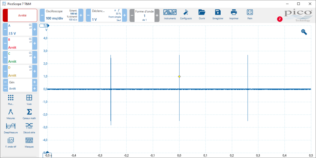
This mechanism dramatically reduces the RF transmitter’s power consumption during idle periods, since it only operates for about 60µs every 256ms (the duty cycle is approximately 0.023%). The only power draw comes from the micro-controller and its supporting circuits.
Enough theory, let’s move on to practice.

Once the product is configured to use LPCD, we can see that the average power consumption is equal to the base consumption of the MCU and its peripheral, below 7mA.
The product still detects easily the approach of the Desfire card. You’d have to be particularly attentive (or very impatient!) to be able to perceive that a little more time than usual (around 260ms) has probably elapsed between the card being inserted and the card being made available in the software (can be observed with PC/SC Diag).
Remark
Some other SpringCard products, like the Prox’N’Drive, which have been specially designed for battery use with very low power consumption, can achieve even lower consumption in LPCD mode, with just a few tens of µA. However, this requires the whole product to be put into deep sleep, which is not compatible with operation as a complete USB device, a requirement for the M519.
What you need to know about LPCD mode
On paper, LPCD mode is brilliant, and you might wonder why all products don’t use it by default. It’s true, at a time when we’re always talking about energy management, why continue to generate the field and run the polling loop forever, if you can do otherwise?
In fact, there is an insoluble flaw in the LPCD, which stems from its very principle. The LPCD relies on the detection of detuning and loading effect. So the card must therefore represent a significant load to the coupler… whereas, ideally, an efficient contactless card must consume as little power as possible, and must cause as little effect as possible on the coupler antenna, so that it can operate at a greater distance from the coupler and not have an operating ‘gap’ even at very short distances. Typically, an ISO/IEC 15693 card that has been optimised for ‘hands-free’ operation with long-distance readers (such as those used in ski resorts or leisure parks), has virtually no impact on the reader under static or quasi-static regime (it’s only the dynamic regime, the small signals of load-modulation, that are useful for making communication work). Small tags (classes 4, 5 and 6 of ISO/IEC 14443-1) will also have less impact on the coupler, because of the lower coupling coefficient between both antennas. The LPCD mechanism will therefore only be able to ‘see’ them at very short distance, where the coupling coefficient increases.
Generally speaking, it is important to keep this rule of thumb in mind: the distance at which a card is detected by the LPCD mode is always shorter (or even much shorter) than the card’s normal operating distance (i.e. the distance at which the card is remotely powered by the reader and the bidirectional communication channel is up and running). If the M519-SUV is installed behind a thick front panel, or if the tags used are particularly small, this can render the LPCD completely inoperative.
It should be noted that to get around this effect, the M519 systematically performs a normal polling loop (with the RF field active, of course) every 2500ms. Doing so, it can still detect a card that has passed under the radar of the LPCD. This behavior slightly increases the average power consumption, but it saves the situation with ‘difficult’ cards. However this remains a source of dissatisfaction for the end-user, as the coupler appears to be dead for more than 2 seconds.

The Dead Parrot is a Monty Python sketch in which John Cleese tries to use a reader that has LPCD enabled, which does not wake up. Michael Palin suggests using a contactless card that beats up the product harder to wake it up. Well, not exactly, but, you’ve got the idea.
Another problem is that the LPCD is only relevant if the electromagnetic environment is stable enough, so the only ‘disturbance’ that can occur is the approach of a card.
Unfortunately, many other events can also modify the impedance seen from the coupler antenna, or fool the system in charge or evaluating its value. This is, of course, the case with any ‘classic’ source of electromagnetic disturbance (motor, electromagnet or relay placed nearby), but we must not forget the potential effects of a poorly filtered power supply, the radiated spectrum of an LCD or TFT panel, or the switching of LED signals to control luminosity and color. In some extreme cases, the product cannot even calibrate its measurement system, because the signal at the antenna terminals is already too variable even during the short calibration burst.
It is therefore essential to know exactly how the product is going to be implemented (and in the case of an OEM product, only the integrator can have this knowledge) before concluding that LPCD mode may be of interest. Otherwise, it simply adds unnecessary latency without having any impact on power consumption.
Conclusion
LPCD is a really powerful mechanism for reducing the power consumption of an M519-based product during the whole phase of waiting for the card to arrive (polling), but you need to be aware of its constraints and limitations.
In many situations, it is sufficient to optimise polling and limit the list of activated protocols to obtain a relatively interesting result with fewer constraints. In concrete terms, if we can reduce consumption to 7mA with the LPCD, we can already get it down to 15mA or even 10mA without the LPCD, with more reliable operation.
In a future article, we will analyse how to optimise the waiting for the card to leave (tracking).